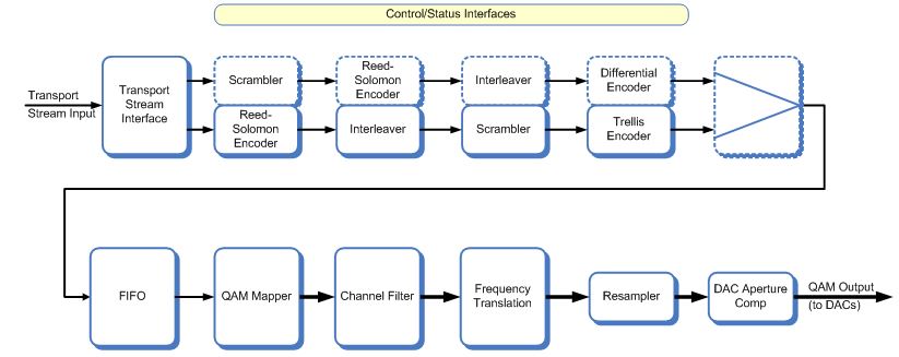
This is a Single-channel Cable Modulator that encodes a transport stream for J83 or DVB-C. The resulting QAM-symbols are filtered and up-converted for output to the radio interface as a single I/Q sample stream for translation to the final RF frequency. Although most designs will implement only one of the cable standards, it is possible to synthesize the core to support any combination of standards in a single device.
Multiple instances of this IP core may be used on an FPGA, sharing access to a single external RAM device. This would typically take the form of a fast SRAM (or possibly SDRAM through a suitable SDRAM controller). Multi-core implementations typically employ separate DACs for each core with the resulting modulated baseband or IF carriers up-converted to the assigned RF frequency bands and combined to produce the wideband cable transmission signal.
A description of the processing steps follows: Forward Error Correction. The FEC is split into an 8-bit datapath for Annex A / C / DVB-C and a second 7-bit datapath for Annex B. The requirements differ to an extent that only the interleaver may be shared between them.
FEC: J.83 Annex A + C and DVB-C. The FEC requirements of J83 Annex A, Annex C and DVB-C are all identical except for supported QAM sizes and the channel filter roll-off parameter. This is a relatively simple FEC, using a scrambler to randomise the data stream for good spectral characteristics, a Reed-Solomon code allowing correction of up to eight byte errors per MPEG packet, and a convolutional interleaver to disperse burst errors over multiple RS codewords.
FEC: J.83 Annex B. The FEC Annex B requires a more complex FEC. In addition to the techniques of scrambling, Reed-Solomon and interleaving used in Annex A, Annex B also includes a trellis code that complements the error-correcting capabilities of the RS code.
FIFO. The QAM Modulator accepts the formatted input stream from the FEC.
Mapper. The data passes through a FIFO into the mapper that selects the appropriate QAM mapping and constellation point. Channel Filter. The selected constellation point is up-sampled and shaped/interpolated by a rootraised cosine FIR filter that can be programmed for the different transition factors (alphas) as required by the supported cable standards.
A resampling interpolation stage provides complex baseband I/Q samples at the desired DAC clock frequency that would normally be a factor of at least 4 times the highest symbol rate to be supported. Frequency Translation. The channel output signal is optionally up converted to a low IF frequency. DAC Aperture Comp. The output is further processed to provide a composite signal to drive compatible DAC devices. This IP can provide parallel complex I/Q signals to input to a pair of DACs, or an interpolating DAC device such as the AD9857, AD9957 or AD9789. Optionally the output can be selected as an IF to supply a single DAC.
Operation: The IP core provides software register settings, e.g. FEC mode and symbol rate. Further software registers are provided to define the IF frequency at the modulator output. When multiple cores are implemented within a single FPGA then each core may be configured independently. This, for example, allows systems to transmit high-order QAM in the more reliable portions of the RF band while simultaneously transmitting low-order QAM on the less reliable frequencies
DAC Aperture Comp. The output is further processed to provide a composite signal to drive compatible DAC devices. The CMS0021 can provide parallel complex I/Q signals to input to a pair of DACs, or an interpolating DAC device such as the AD9857, AD9957 or AD9789. Optionally the output can be selected as an IF to supply a single DAC.
